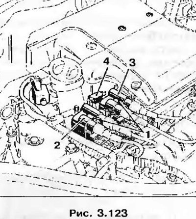
- injection computer (the power stage of the ignition module is built into the computer);
- two ignition coils with two leads;
- four spark plugs;
- noise filter capacitor 4.
Principle of operation
The injection computer, based on information received from the sensors, but mainly depending on the crankshaft speed and engine load, determines:
- the value of the advance angle and, accordingly, the moment of ignition;
- the location of the cylinder pistons at top dead center and, accordingly, the ignition coil, to which it sends a low-voltage pulse.
The impulse causes a spark discharge on the spark plugs in two cylinders, the pistons of which are at TDC, breaking contact with the ground of the corresponding ignition coil.

Ignition coil 2 has a black electrical connector. It generates high voltage pulses to the spark plugs of cylinders 1 and 4, with the spark discharge occurring simultaneously on both spark plugs. The ignition coil is controlled via channel 28 of the injection computer.
Coil 3 has a gray electrical connector. It generates high-voltage pulses on the spark plugs of cylinders 2 and 3, with a spark discharge occurring simultaneously on two spark plugs.
The ignition coil is controlled via channel 29 of the injection computer.
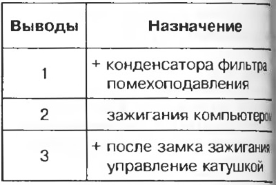
Electrical connector
Table 3.10

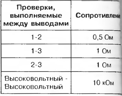
Table 3.11

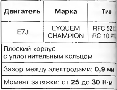
Spark plug
Table 3.12

