
Check the presence of thrust half rings on the 3rd support (the grooves of the half rings must face the cheeks of the crankshaft).
Note. The mating surfaces of the cylinder block and main bearing cap 1 must be clean, dry and free from oil (don't touch them with your fingers).
Note. Applying too much sealant can cause it to be squeezed out when parts are tightened. The ingress of sealant into working fluids can lead to damage to some components and assemblies (engine, radiator, etc.).
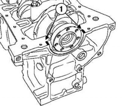
Pic. 2.166. Sealing locations: 1 - sealant
Apply two swabs of RHODORSEAL 5661 (or its equivalent) 1 mm wide per support 1 (pic. 2.166).
Install the crankshaft main bearing caps with cap 1 on the flywheel side.
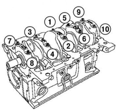
Pic. 2.149. The order of tightening the bolts of the crankshaft main bearing caps
Tighten in order to the correct torque (25 Nm + 47°±5°) and tighten the crankshaft main bearing cap bolts to the required angle (see fig. 2.149).
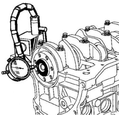
Pic. 2.167. Checking the axial movement of the crankshaft
Check the axial movement of the crankshaft (pic. 2.167).
Axial movement with new thrust half rings is 0.045–0.252 mm.
The axial displacement with the thrust half rings operated is 0.045–0.852 mm.
Make sure that the crankshaft rotates freely without binding.