Attention! Together with the belt, be sure to replace the tension and bypass rollers.
Note. The procedure for removing and installing the timing belt for engines with or without a camshaft dephaser is the same.
Removing
Place the car on a two post lift.
Disconnect the battery.
Remove the engine undertray.
Remove the accessory drive belt.
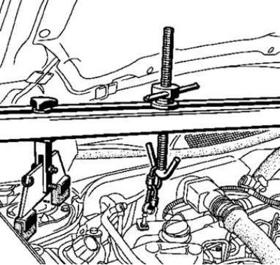
Pic. 2.41. Installation of special devices
Install special tools (Mot. 1453 and Mot. 1453-01) with holding straps (pic. 2.41).
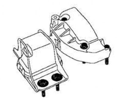
Pic. 2.42. Marking the pendulum supports
Mark the position of the pendulum support in relation to the body (pic. 2.42).
Remove the engine swing arm mount assembly with the top bracket.
Remove the lower jet link.
Attention! Be careful not to damage the air conditioner piping.
Remove the intake silencer mounting bolts.
Remove the intake silencer.
Poke through the center of the camshaft plugs with a screwdriver.
Remove the camshaft caps with screwdrivers.
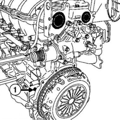
Pic. 2.43. Location of the hole plug for the TDC lock: 1 - cork
Remove the hole plug for the TDC lock (pic. 2.43).
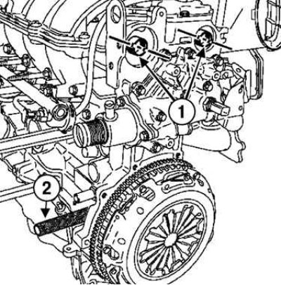
Pic. 2.44. Installing the TDC lock: 1 - grooves of camshafts; 2 - TDC lock
Position the camshaft grooves horizontally and offset downwards from the shaft axes, turning the crankshaft in the direction of rotation (clockwise as viewed from timing end) (pic. 2.44).
Screw in the TDC lock (Mot. 1489).
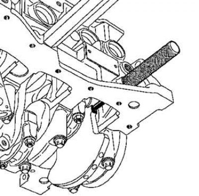
Pic. 2.45. Turning the crankshaft clockwise
Turn the crankshaft clockwise (viewed from the timing side) all the way to the TDC lock (pic. 2.45).
Make sure that the grooves on the ends of the camshafts are horizontal and below the axes of the shafts.
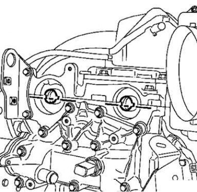
Pic. 2.46. Checking the position of the grooves on the ends of the camshafts
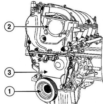
Pic. 2.47. Removing the crankshaft pulley, upper and lower timing cover: 1 - crankshaft pulley; 2 - the top cover of the timing drive; 3 - the lower cover of the timing drive
Remove the crankshaft pulley by blocking the flywheel with a screwdriver, the upper and lower timing covers (pic. 2.47).
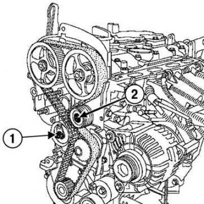
Pic. 2.48. Removing the bypass roller using a special tool: 1 – a nut of fastening of an axis of a tension roller; 2 - bypass roller
After releasing the nut securing the tension roller axle, loosen the tension of the timing belts (pic. 2.48).
Remove the bypass roller using the special tool.
Remove the timing belt, being careful not to drop the crankshaft sprocket.
Remove the crankshaft sprocket.
Remove the tension roller.
Installation
Attention! Replace the timing belt, crankshaft pulley bolt, idler and bypass rollers.
Attention! Degrease the end of the crankshaft (from the timing drive), as well as the hole and bearing surfaces of the pulley, the crankshaft sprocket and the crankshaft itself.
Attention! This must be done so that the timing drive does not move, otherwise the engine will fail.
Attention! Such a displacement leads to engine failure.
Position the camshaft grooves horizontally and offset downwards from the camshaft axes, turning the camshafts if necessary using the special tool (Mot. 799-01).
Install on fixture (Mot. 1496) adaptation (Mot. 1750).
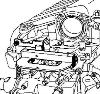
Pic. 2.49. Installation of special devices on the ends of camshafts
Install fixture (Mot. 1496) with fixture (Mot. 1750) at the ends of the camshafts (pic. 2.49).
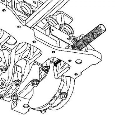
Pic. 2.45. Turning the crankshaft clockwise
Install the TDC lock (Mot. 1489) (see fig. 2.45).
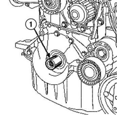
Pic. 2.50. Checking the position of the crankshaft groove: 1 - groove
Make sure the crankshaft is locked with the TDC lock (Mot. 1489), and the groove of the crankshaft is facing up (pic. 2.50).
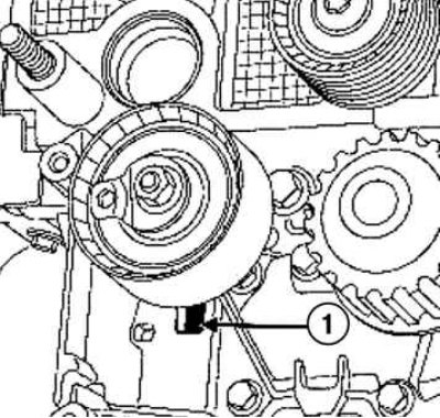
Pic. 2.51. Tension roller installation: 1 - groove
Install the tension roller, placing its protrusion in the groove (pic. 2.51).
Install the crankshaft sprocket, timing belt and idler pulley.
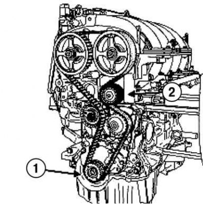
Pic. 2.52. Installing the crankshaft sprocket, timing belt and idler roller: 1 - toothed pulley; 2 - bypass roller
Tighten to specified torque (45 Nm) bypass roller bolt with special tool (Mot. 1368).
Belt tension
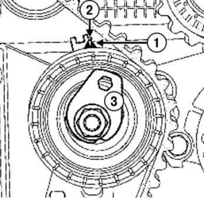
Pic. 2.53. Belt tension: 1 - pointer; 2 - notch; 3 - eccentric
Using a 6mm Allen wrench, align the movable pointer with the notch by turning the eccentric clockwise (pic. 2.53).
Torque tighten (27 Nm) nut of fastening of an axis of a tension roller.
Install the pulley on the crankshaft.
Tighten to the required torque and tighten to the specified angle (crankshaft must be locked with TDC lock) crankshaft pulley bolt (40 Nm+145°±15°).
Remove the camshaft locking tool (Mot. 1496).
Remove the TDC retainer (Mot. 1489).
Rotate the crankshaft two turns clockwise (viewed from the timing side).
Before the end of the second revolution, tighten the TDC lock (Mot. 1489) into the hole in the cylinder block.
Slowly, without jerking, tighten the crankshaft until it stops at the TDC lock.
Unscrew the TDC lock (Mot. 1489).
Make sure the movable pointer is against the notch.
Loosen the idler pulley mounting nut, no more than one turn, while holding the movable pointer with a 6 mm hex wrench.
Slowly move the movable pointer to align with the notch by turning the eccentric clockwise.
3torque (27 Nm) nut of fastening of an axis of a tension roller.
Checking the installation of the valve timing and timing belt tension
Align the movable pointer with the fixed pointer or with the notch, depending on the tensioner version.
Torque tighten (27 Nm) nut of fastening of an axis of a tension roller.
Before checking the installation of the valve timing, make sure that the tension roller pointers are in the correct position.
Screw the TDC lock (Mot. 1489) into the bore of the cylinder block.
Slowly and without jerking, bring the crankshaft to the stop against the latch.
Install (without making an effort) adaptation (Mot. 1496) for fixing camshafts (the grooves of the camshafts must be in a horizontal position below the axes of the shafts.
Attention! If the camshaft locking tool does not snap into place, reinstall the timing and timing and adjust the timing belt tension.
Remove the TDC lock.
Table 2.6. Necessary fixtures and special tools
| Marking | Name |
| Mot. 1453 | Adjustable support bar with retaining straps for hanging the engine |
| Mot. 1453-01 | Additional nut with handle for engine jack Mot. 1453 |
| Mot. 1439 | TDC lock |
| Mot. 1368 | Tool for tightening the eccentric bolt of the tension roller. Key «Torx» on «8» and head on «12.7» |
| Mot. 799-01 | Camshaft pulley retainer |
| Mot. 1496 | Camshaft Locking Tool |
| Mot. 1750 | Adapter for camshaft locking tool Mot. 1496 |
| Mot. 1490-01 | Tool for fixing the camshaft pulleys |
| Mot. 1487 | Camshaft cover installer (diameter 57 mm) |
| Mot. 1488 | Camshaft cover installer (diameter 43 mm) |
Table 2.7. Tightening torques when removing and installing the timing belt
| Element | Tightening torques, Nm |
| Bypass roller mounting bolt | 45 |
| Nut of fastening of an axis of a tension roller | 27 |
| Bolt of fastening of a pulley of a cranked shaft | 40, then tighten by 145°±15° |
| Nut of fastening of an axis of a tension roller | 27 |
| New camshaft pulley nuts | 30, then tighten 84°±4° |
| Plug hole for TDC lock | 20 |
| Bolts and nuts for fastening the upper cover of the timing drive | 41 |
