
Most fuses are installed in the fuse box located in the passenger compartment (Fig. 10.1), at the left end of the instrument panel under the plastic cover. The circuits protected by the fuses are listed in Table 10.1.
Circuits protected by fuses
Table 10.1.
| Fuse number (see fig. 10.1) | Fuse rating, A | Protected circuit |
| F1 | 20 | Windscreen cleaner |
| F2 | 5 | Instrument cluster, ECU |
| F3 | 10 (20*) | Brake light switch, Reverse light switch |
| F4 | 10 | Electronic engine start interlock (airbag and seat belt pretensioner control unit*) |
| F5 | 10 | Automatic transmission |
| F7 | — | Trailer |
| F9 | 10 | Left headlight (low beam) |
| F10 | 10 | Right headlight (low beam) |
| F11 | 10 | Left headlight (high beam) |
| F12 | 10 | Right headlight (high beam) |
| F13 | 30 | Rear electric windows |
| F14 | 30 | Front electric windows |
| F15 | 10 | ABS control unit |
| F16 | 15 | Electric heated front seats |
| F17 | 15 | Sound signal |
| F18 | 10 | Left side marker light, hazard warning switch, cigarette lighter |
| F19 | 10 (7,5*) | Starboard side marker light |
| F20 | 7,5 | Rear fog light switch |
| F21 | 5 | Electrically heated exterior rear view mirrors |
| F23 | — | Place for installation of security alarm |
| F24 | 5 | Power steering |
| F25 | 5 | Gas equipment |
| F26 | 5 | Airbag and seat belt pretensioner control unit |
| F27 | 20 | Rear wiper, reversing light switch |
| F28 | 15 | Interior lighting |
| F29 | 15 | General nutrition |
| F30 | 20 | Locking opening body elements |
| F31 | 15 | Fog lights |
| F32 | 20 | Electrically heated rear window |
| F36 | 30 | Electric fan of the heating system (air conditioning) and ventilation of the cabin |
| F37 | 5 | Electric drive of outside rear view mirrors |
| F38 | 15 (10*) | Car radio |
| F39 | 10 (30*) | Heating systems (air conditioning) and ventilation of the cabin |
* Only for vehicles produced before 2009.
Note: F6, F8, F22, F33-35 - reserve.
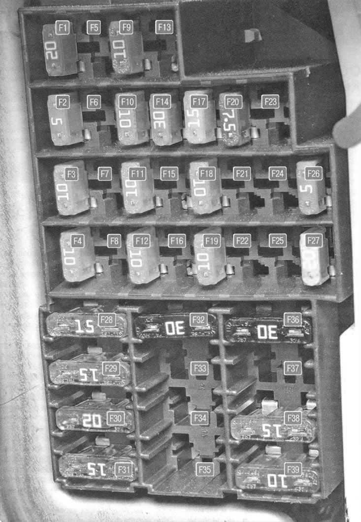
Fig. 10.1. Fuse numbers in the fuse box located in the passenger compartment
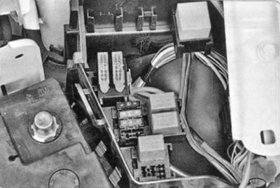
In addition, relays and fuses are located in the mounting block in the engine compartment (Fig. 10.2).
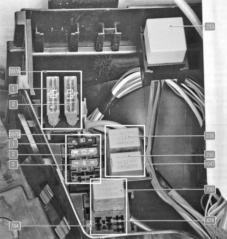
Fig. 10.2. Relay and fuse numbers in the mounting block located in the engine compartment (K7J engine)
Table 10.2 shows the block designations and the purpose of the installed relays and fuses.
The purpose of the relays and fuses in the mounting block located in the engine compartment
Table 10.2.
| Relay/Fuse Box | Relay/Fuse Number (current strength, A) | Purpose of relay/fuse |
| 597A | F1 (60 A) | Security alarm, outdoor lighting switch, daytime running light relay |
| F2 (60 A) | Exterior Light Switch, Interior Fuse Box | |
| 597B | F1 (30 A) | Power supply for the relay board |
| F2 (25 A) | Fuel injection system relay power supply circuit | |
| F3 (5 A) | Fuel injection system relay power supply circuit, engine control unit | |
| 784 | 474 (20 A) | Air conditioning compressor relay |
| 700 (20 A) | Electric Fan Relay | |
| 1047 | 236 | Fuel pump relay |
| 238 | Injection lock relay | |
| Separate relay | 233 | Heater Fan Relay |
It should be borne in mind that, depending on the vehicle configuration, there may be differences in the layout of the mounting blocks and the absence of some circuits indicated in the table.
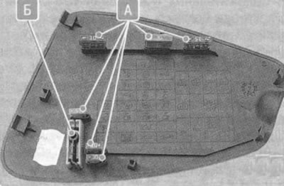
1. To gain access to the mounting block located in the passenger compartment, remove the cover in the instrument panel.
Note.
- The inside of the cover has a diagram of the fuse locations. The cover also contains spare fuses A of various ratings and plastic tweezers B for removing fuses from the mounting block.
2. Before replacing a blown fuse, find out the reason for its blown fuse and eliminate it. When searching for a fault, look at the circuits specified in Table 10.1 that this fuse protects.
Warning: Do not replace fuses with jumpers or fuses rated for a different amperage or homemade jumpers - this may damage electrical equipment and even cause a fire.
3. Remove the replacement fuse using special tweezers.
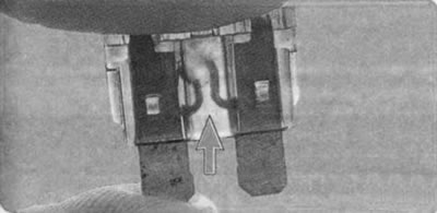
4. This is what a blown fuse looks like (the jumper shown by the arrow inside the holder has burned out and opened). To replace a fuse, use a spare fuse of the same rating (and colors).
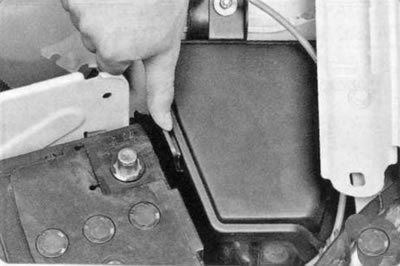
5. To access the vehicle's mounting block, located in the engine compartment, press the latch...
6....and remove the mounting block cover.
7. If replacement is necessary, remove the relay (fuse), swinging it from side to side.
8. Install the parts in the reverse order of removal.