
You will need: keys «by 10», «at 12», «at 17», spark plug wrench, magnetized screwdriver (or tweezers) for removing valve spring crackers, device for compressing valve springs.
1. Remove all spark plugs (see «Replacement and maintenance of spark plugs»).
Note. The procedure for disassembling, repairing and assembling the cylinder head is shown using the K7J and K7M engines as an example. Disassembling, repairing and assembling the cylinder head of the K4M engine is carried out in a similar manner. The only difference is that the K4M engine does not have a rocker shaft and has two camshafts (see «Replacing the camshaft»).
2. Unscrew the three mounting nuts and remove the exhaust manifold heat shield.
3. After unscrewing the remaining nuts securing the exhaust manifold, remove the manifold and the gasket installed underneath it (see «Replacing the exhaust manifold gasket»).
4. Unscrew the four upper bolts securing the intake pipe to the cylinder head, unscrew the three lower nuts and remove the intake pipe together with the throttle assembly and fuel rail (see «Replacing the intake manifold seal»). Remove the intake manifold sealing gaskets.
Note: Replace the intake manifold gaskets with new ones each time the connection is disassembled.
5. Unscrew the three mounting bolts and remove the thermostat (see «Removing and installing the thermostat»).
6. Remove the valve rocker shaft assembly with the rocker arms and the camshaft (see «Replacing the camshaft»).
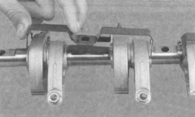
7. If necessary, remove the rocker arm clamps from the axle...
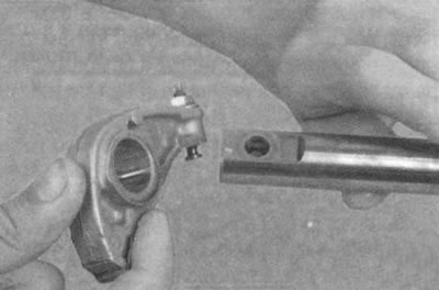
8....and valve rocker arms.
Note: If you are not replacing the rocker arms, their shaft, and the camshaft, do not remove the rocker arms from the shaft so that they can be installed in their original positions during assembly.
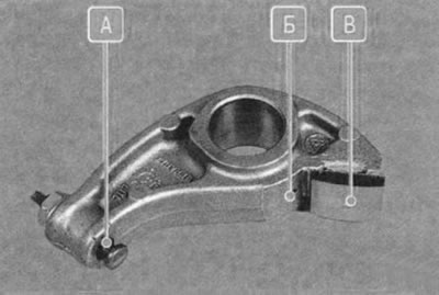
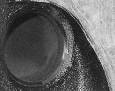
9. Inspect the valve rocker arms. Replace the rocker arm if there is severe, clearly visible wear on surface B that contacts the camshaft lobe. Check the cleanliness of hole B for supplying lubricant to the camshaft lobe. Check the condition of the head of adjusting bolt A and, if there are clear signs of wear on it...
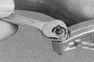
10....unscrew the bolt lock nut...
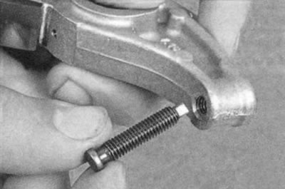
11....and unscrew the bolt from the rocker arm.
Note: On the K4M engine, check the wear of the hydraulic valve lifters and replace them with new ones if necessary.
12. Install the valve spring compressor, compress the springs, remove the crackers, spring plates, springs (see «Replacing valve stem seals») and remove the valves from the guide bushings.
Warning. After prolonged use, a mushroom-shaped burr may form on the upper end of the valve. Before removing the valve from the guide bushing, remove this burr with a file. It is strictly forbidden to knock the valve out of the guide bushing with a hammer through a mandrel without removing the burr, since this will inevitably damage the inner surface of the bushing
13. Remove resinous deposits from the top surface of the head and from the intake ports. These deposits can be softened and washed off with kerosene or diesel fuel.
14. Clean the combustion chambers and exhaust channels from carbon deposits. Remove carbon deposits with a round metal brush installed in the chuck of an electric drill.
Helpful tips:
- First, soak the carbon deposits with kerosene.
- Use caution: Avoid inhaling dust generated during combustion chamber cleaning.
- To prevent dust formation, periodically wet the carbon deposits with kerosene.
15. Clean the inside surfaces of the valve guides with a thin cylindrical copper wire brush clamped in the chuck of an electric drill.
16. Remove any burnt-on remains of the sealing gasket from the mating surface of the head to the cylinder block.
Warning: Do not clean the head mating surface with wire brushes or sandpaper. Use a hardwood or plastic spatula after softening the gasket residue with solvent.
17. After cleaning, inspect the cylinder head to prevent its operation with damaged threaded holes or cracks (especially between valve seats and in exhaust ports), corrosion, inclusions of foreign materials, cavities and fistulas.
18. Using a feeler gauge and a metal ruler installed on its edge, check the flatness of the surface of the head mating to the block in the longitudinal and transverse directions, as well as diagonally. If the gap between the edge of the ruler and the surface of the head exceeds 0.05 mm, replace the head.
19. Clean the surfaces of the head flanges for installing the intake pipe and exhaust manifold from gasket residues and carbon deposits.
20. Check for deformation of the intake pipe and exhaust manifold mounting flanges; replace the deformed head.
21. Repair damaged threaded holes by tapping the threads or installing a repair sleeve (insert).
22. Determine the wear of the valve guide bushings by measuring the inner diameter of the bushing hole and the diameter of the valve stem and determining the clearance based on the difference between these dimensions. The maximum allowable clearance for wear for intake valves is 0.10 mm, for exhaust valves - 0.15 mm.
23. If the clearance remains greater than the maximum permissible value even when installing new valves, replace the guide bushings. Replace the guide bushings in a specialized workshop with the appropriate tools and equipment.
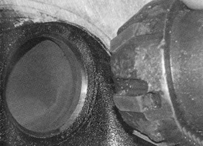
24. Check the condition of the valve seats. There should be no signs of wear, cavities, corrosion or other defects on the working chamfers of the seats. The valve seats can be replaced in a specialized workshop. Minor damage (minor scratches, marks, etc.) can be removed by grinding the valves (see «Lapping valves»).
25. More significant defects of valve seats are eliminated by grinding. Seats must be ground in a specialized workshop, as this requires special tools and equipment. If significant defects of seats cannot be eliminated by grinding, replace the seats.
26. Remove carbon deposits from the valves and inspect them. Deformation of the stem 1 (Fig. 5.13) valve and cracks on its plate 2 are not allowed. If there is damage, replace the valve. Check whether the working chamfer 3 is too worn or damaged. Grinding the working chamfer of the valves is allowed (in repair shops with the appropriate equipment). After grinding, the thickness of the cylindrical part of the plate should be at least 0.5 mm for inlet valves and at least 1.0 mm for outlet valves. Minor scratches and marks on the chamfer can be removed by grinding the valve to the seat (see «Lapping valves»)
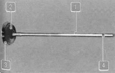
Fig. 5.13. Valve: 1 - rod; 2 - plate; 3 - chamfer; 4 - groove
Warning: To prevent scratches from forming on the valve stems, do not clean them with wire brushes or metal scrapers.
27. Check the concentricity of the valve plate and seat: apply a thin layer of paint to the chamfer of the valve head (for example, Prussian blue), insert it into the guide sleeve and, pressing it lightly against the seat, turn it. The traces of paint on the chamfer of the seat can be used to judge the concentricity of the valve and seat.
28. Check the condition of the valve stem grooves for the crackers. If traces of chipping of the groove edges and wear of the cylindrical part are found, replace the valve.
29. Replace the oil seals regardless of their condition.
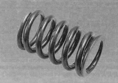
30. Inspect the valve springs. Cracks and loss of elasticity of the springs are not allowed. Springs of one of two types can be installed. The nominal length of the first type of spring in a free state (46,5±2) mm, the second type - (46,64±2) mm. The length with fully compressed coils is 26.0 and 23.63 mm, respectively. Springs whose length in a free state is less than the maximum permissible value, as well as curved springs (the deviation of the spring axis from the vertical in a free state is more than 4°) and replace the ones with cracks.
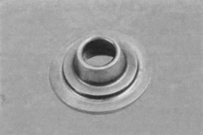
31. Check the condition of the spring plates. Replace the plates with significant wear of the spring support grooves.
32. Install all removed parts and assemblies of the cylinder head in the reverse order of removal.
33. Always replace the cylinder head, intake manifold and exhaust manifold gaskets with new ones, since gaskets removed from the engine, even if they are not damaged externally, may be heavily compressed and will not provide a tight seal.